
Parameters defining the selection using non gaseous fluids
The selection of the most suitable heat exchanger for a certain thermal task requires to know some parameters of the process, such as the properties of the involved fluids, their specific heat, the thermal load engaged, the maximum fluids flow rate, their inlet and outlet temperatures (in other words, the thermal gap between them), pressures, temperatures and maximum pressure drops allowed by the process.
In order to decide the right size of the exchanger, it is important to know the overall thermal exchange rate, which is based on the kind of fluids employed, the kind of exchanger involved, the speed of fluids and the turbulent or linear regime of the fluids within the exchanger. Fouling factors, maintenance needs and the further possibility of a future boosting complete the elements to take in account during the selection of a heat exchanger.
PRESSURES AND TEMPERATURES
There are limits of use of a heat exchanger related to temperature and pressure range of the fluids employed by the thermal machine, that must be envisioned for a correct and proper selection of the type of exchanger.
INSPECTABLE PLATE HEAT EXCHANGERS
- Maximum working pressure 25 bar
- Maximum working temperature 190° C
BRAZED PLATE EXCHANGERS
- Maximum working pressure 40 bar (only for some models)
- Maximum working temperature from 250 up to 900° C (depending on models)
Brazed shell and plate exchangers could be a good alternative for more demanding working conditions, combining the advantages of shell and tube exchangers and plate heat exchangers: high pressure and temperature gaps, low pressure drops, reduced weights and sizes, completely welded but also offering easy maintenance and cleaning.
In this case, as with tube heat exchangers, pressure and temperature limits increase significantly compared to the range allowed by normal plate heat exchangers. This feature makes them an ideal solution in oil & gas and heavy chemical industry process applications.
Brazed plate heat exchangers can be the ideal solution for high pressure temperatures requirements (40-45 bar and full vacuum) and very wide temperature ranges (-200° C and up to +300° C). The welding of the plates among them ensures indeed an optimal mechanical strength to this kind of exchangers (in a normal plate heat exchanger, mechanical strength is achieved bay mounting the adjacent plates with corrugations in opposite directions, in order to obtain several crossing and contact points between them).
FLUID’S SPEED
A factor that highly affects the overall thermal transfer efficiency of a heat exchanger surely is the speed of the fluids flowing within it. Usually, structure, geometry and sizes of the exchanger and its positioning have to be designed in order to give a turbulent movement to the fluids, boosting the thermal transfer that is not achieved properly with a laminar flow.
Excessive high speed must be avoided, anyway, because they can lead to an uncontrolled increase of pressure drops, and foster corrosion effects in case of dirty fluids or with particle in suspension.
Using changing phase fluids, typically happening with exchangers employed as condensers or evaporators, requires a more accurate evaluation of fluid’s speeds in order to avoid the drag of droplets that can compromise the functioning of the equipment (for instance, when the complete condensation or evaporation of the fluid is crucial to the process, as in the application of heat exchangers in form of vent trap on reactors).
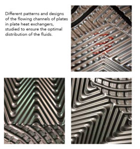
In plate heat exchangers, a trick to increase fluid’s turbulence is the corrugation of the plates, which entails an increase in thermal transfer coefficients. Furthermore, plates of more modern conception are designed with special geometries and patterns aimed to achieve a more uniform flow on the plate’s surface, using chevron angles and the ‘chocolate pattern’, the fluid’s distribution area in inlet and outlet, which have passage sections of the fluids with shorter channels and a smaller section, or longer channels with bigger section.

 Back to index
 Download the complete book