
Cogeneration and thermal machines
Cogeneration is a widely employed power generation system for the combined generation of electric energy and thermal energy, in form of heat/cold. It allows to use at maximum the rendition of endothermic engines within generators, increasing their efficiency by 40-45%, reaching an overall efficiency rate of 90%. This can be achieved thanks to thermal machines employed for heat recovery on heat generated by the engines, through exhaust fumes recovery, from cooling water on engines’ jackets or from the after cooler circuit.
The heat recovery can be maximized using dedicated pre-mounted package skids, equipped with all the components aimed to ensure a reliable and automatic functioning.
These prefabricated modules usually include:
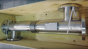
- Heat exchanger for exhaust recovery, rods cleaning type, complete with thermal expansion joint on shell and heads in anti-corrosion material
- Plate heat exchangers for heat recovery on engine’s cooling water
- Circulating pump
- Monitoring devices
- Exhaust by-pass valve (if exhaust are not recovered, the fumes are diverted from the exchanger)
- Thermostatic valve switching to the emergency dissipation system
When there is no need of waste heat recovery, it’s also necessary to integrate the plant with an emergency dissipation system, equipped with electro radiators that provide the dissipation of heat generated by the engine.
All of these components must be carefully selected and fine-tuned, otherwise failures are possible causing even serious damages to the engine.
The waste thermal heat recovery system on a cogeneration plant must indeed be very carefully engineered, because a wrong engineering of the heat recovery plant could lead to many issues. There are indeed some factors to consider both during the design phase and the functioning of the system. During the design and engineering, it’s very important to evaluate the temperatures and stresses inducted on the components in charge of the thermal transfer process.
During the functioning of the plant, there is a series of procedures to undergo in order to ensure safe operations. A cogeneration plant is intended for a continuous functioning, for long periods. Regularly planned preventive controls are therefore necessary, requiring careful and scrupulous controls.
Due to the high temperatures involved and the operating conditions of a exhaust recovery plant, even a small underestimated detail can lead through time to huge damages, that could require high restoration costs. Vibrations, expansions, bolts strengthening, gaskets and seals are a few among the elements that require a constant control and monitoring.
To simply explain it to our customers, we often bring this example: considering a workload of 8.000 hours/year, if the plant was a car traveling at 50 km/h, it should mean that it travels at least 400.000 km per year. How many servicing checks this car would have had? And most of all, it would still be traveling?
In a cogeneration plant, it is advantageous to achieve maximum efficiency possible in terms of heat recovery on oil and water. The recovery on waste exhaust is a different matter. This is in fact a very smart recovery, because it operates on a very high temperature fluid, and thus even when having low flow rates (in mass quantity), it is possible to achieve an excellent thermal recovery using a shell and tube exchanger. But cogeneration plants with endothermic engines can be powered using a series of different fuels:
- Gasoline
- Natural gas (methane)
- Biogas from farm animal waste
- Biodiesel
- Landfill biogas
The kind of fuel employed becomes here a crucial factor for the selection of both the components and the heat exchanger aimed for exhaust recovery. Each of the kind of fuel employed entails indeed different fouling factors to evaluate for the selection of the diameter of tubes. In addition, it’s important that the exchanger is suitably sized, and not over-sized. This is important because a generous sizing of the exhaust recovery circuit lead to a dramatic decrease in the output temperature of the fumes coming out from the exchanger. It will therefore cause a likely increase in condensation which, based on the kind of fuel employed, will be more or less acidic, then increasing the risk of corrosion on the exchanger.
Heat recovery on exhaust are usually achieved trying to obtain an output temperature of the fumes not under 130° C (an approximate value that vary based on the kind of fuel). Anyway, these are the golden rules for the proper engineering of a heat recovery system in a cogeneration plant:
- Straight pipes enabling rods cleaning operations
- Tubes and head in AISI 316 stainless steel
- Removable head for easy disassembling
- Expansion joint on the shell
Also, think about integrating the plant with a reliable bypass valve for the exhaust fumes, able to withstand working temperatures of 600° C and even higher.
Furthermore, the employ of cogeneration groups is nowadays more and more applied in waste dumps and livestocks. That’s because it represents a truly valid energy saving solution, clearly due to the fact that biogas engendered by waste or by the animals’ livestocks waste is an optimal source of alternative energy. Anyway, the gas produced here cannot be directly employed within an engine, because it’s humid and full of acid and corrosive condensations. Therefore, it needs to be dehumidified. Otherwise, when entering endothermic engines, it would cause a bad functioning and leading to unrepairable damages in a short period of time.
In order to make it less aggressive and suitable for these kind of engines, all of the these plants are then equipped with high-performing dehumidification systems, including a combination of:
- Refrigerator
- Shell and tube condenser
In fact, the biogas comes in from a blower at +40 / 45° C, and entering a shell and tube exchanger fed on the secondary circuit by a mix of water and antifreeze at temperatures near 0° C. It allows to condensate almost all of the humidity within the biogas, putting outwards from the shell and tube exchanger the biogas at approx. +3 / +4° C and saturated, meaning with a relative humidity of 100% but with extremely low values of absolute humidity. After a final heating cycle, made using another blower or other systems, the biogas is ready to feed the engines.
Another problem is caused by the increasing use of palm oil and other vegetable oils within cogeneration plants. This kind of fuels have a very high viscosity at ambient temperature, near to a gelatinous texture. That’s why these kind of plants often employs a double feeding circuit: they start-up using gasoline, and then switch the palm oil fueling.
Anyway, palm oil must be kept warm inside the tank, and it is possible to adopt different solutions: electric resistors directly in the tank or coils fed with hot water. Here, the best solution is to employ TCOIL immersion plate heat exchangers, shaped ad hoc and directly immersed in the tank, leveraging the manhole and feeding them with hot water. Perhaps also recovering the hot water coming directly from engine’s jackets, in line with the green approach of a cogeneration plant achieving a first, even if limited, energy recovery.
At last, energy recovery performances of a cogeneration plant are strictly depending from a series of factors:
- Amount of heat produced
- Temperature of the heat source
- Kind of thermal vector
- Working fluid
The kind of working fluid in a thermal recovery system of a cogeneration plant is in particular a crucial aspect speaking about the optimization of the thermodynamic circuit. It must be selected referring to the temperature of the primary source of waste heat.

 Back to index
 Download the complete book